ASSEMBLY DRAWINGS

ASSEMBLY DRAWING SERVICES

Assembly drawing is a presentation of a structure or product with its components connected together,in their relative working positions while in use. These components are fabricated separately, and are assembled or installed together at their utility sites such that each part fits and matches with the others. Advenser has a unique track record of a decade, delivering assembly drawings for architectural, structural, mechanical and plumbing systems to the AEC and manufacturing industries.

Mechanical GA drawing

Our experienced engineering detailing team ensures that, the assembly drawings we produce depict precise information for the site workers to assemble the components seamlessly. Our 3D modeling services for an assembled structure or product convey its final shape. We also provide a Bill Of Materials list, which is a list of component parts that communicate dimensions, shapes and labeling of individual components.

Architectural Overall Layouts

Architectural floor plan

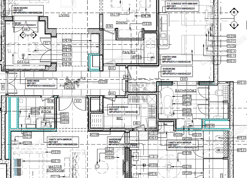
Architectural general layouts or assembly drawings detail how the different prefabricated components connect with each other, and with the structural elements. Advenser has rich and versatile experience record working in general layout arrangements for individual architectural elements such as doors or windows, as well as architectural sub-assemblies such as roof trusses or millwork for residential, commercial and institutional projects. 3 Dimensional views are also provided by us to illustrate the correlation between individual elements and trades involved. We warrant that our assembly drawings contain an optimum and comprehensive measure of details necessary for laymen to install the architectural system in the built environment, at the same time avoiding unnecessary and irrelevant details.


Our Architectural Assembly Drawing Services:

Doors & Windows

Joinery

Roof trusses

Millwork

Masonry & Brickwork

Floor & Wall Panel systems

Mechanical Assembly Drawings

Mechanical assembly drawings are produced to communicate how the various parts of a product or machine fit together in their working condition, and paint its completed overall shape and dimensions. Relative movements of individual components in the assembly are depicted by phantom lines. We also provide exploded views to convey correct order of assembly and pictorial directions for accurate alignment of components. Parts list are generated to provide a complete list of all parts needed to complete the project. Item numbers matching the parts list are shown as identification balloons.

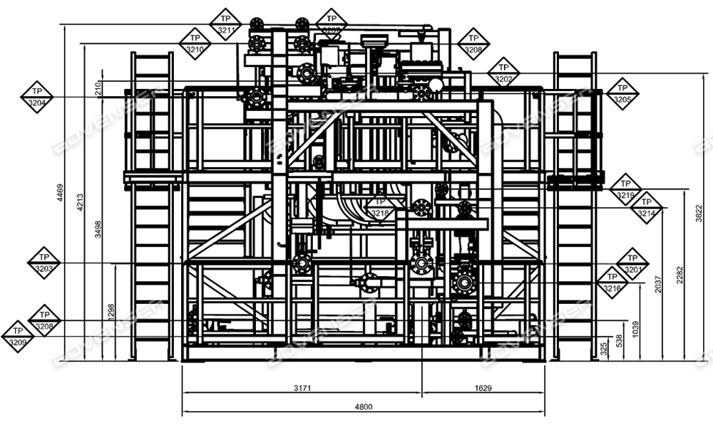
Mechanical Assembly Drawings Offered:

Design Assembly Drawing

Sub-Assembly Drawing

Assembly Drawings for Catalogues & User Manuals

Detailed Assembly Drawing

Installation Assembly Drawing

Schematic Assembly Drawing

Mechanical general assembly drawing

HVAC & Plumbing Spool Maps

Mechanical spool drawing
Spool Drawings provide the directional guidance for prefabrication and assembly of Mechanical & Plumbing systems. At Advenser, we generate spool drawings for HVAC Pipes, Ducts & Plumbing from a coordinated 3D BIM Model. Our model provides a 3 Dimension view of the assembly, and how the individual elements and sub assemblies interconnect. The spool maps we create is optimized with all relevant information for installation team to assemble accurately. Our MEP modelers ensure that the drawings are made in compliance with international standards and custom instructions from the client. Our Spool Drawings provide guidelines and directions for seamless fabrication and installation.

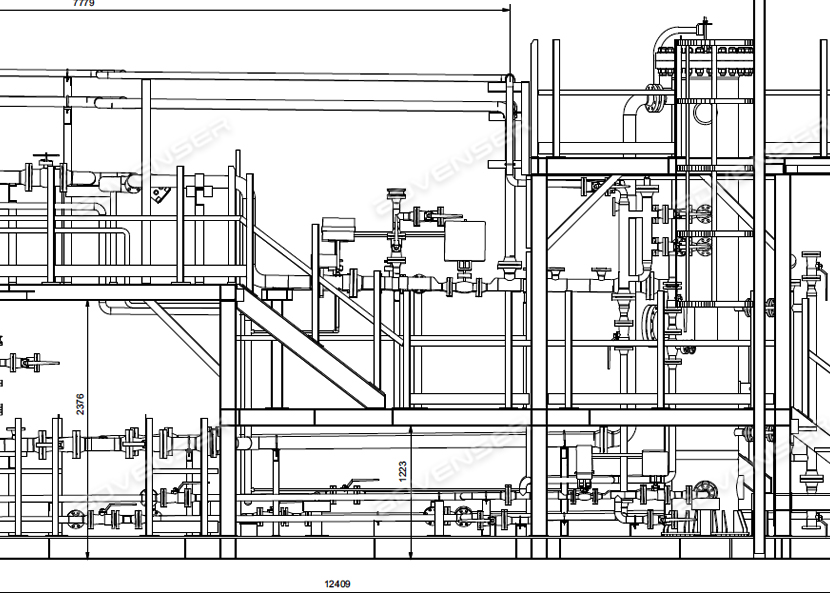
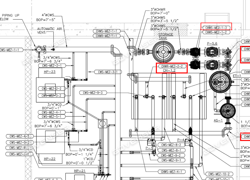
Our Spool Drawing Services:

HVAC Pipe

Duct

Plumbing

Steel Assembly Drawings

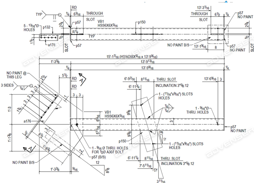
Steel Assembly drawings are part of fabrication drawings and show how the individual steel members such beams, columns or plates are welded to each other. Our Steel Assembly drawings accurately detail the sizes, relative positions, hole position, finish details and part numbers of each steel members in the assembly. We adhere to strict quality measures in the production steel fabrication shop drawings, assembly drawings and erection drawings. Our Steel detailers utilize leading software tools that provide 3D modeling capabilities such as Trimble Tekla and Advance CAD for generating integrated clash free structural models. Assembly drawings and shop drawings are extracted along with Structural & Miscellaneous steel Take off lists (Bill of materials).

Our Steel Fabrication Drawing Services:

Assembly drawings

Steel Take off

Parts Shop drawings

steel Assembly drawing

Shop Drawings for Precast Assemblies

Architectural precast
GA drawings or Erection drawings illustrate the general framework of individual precast elements and provide member piece marks, sizes, shapes and locations of each.
At Advenser, our precast detailing team take care to model beams, columns and slabs accurately and to careful identify the joints and opening between members, based on design drawings and contract documents. We use BIM tools such as Tekla and Revit to show the 3D views of connection between precast elements and also to other structures. They aid the erection crews in intuitive erection giving them accurate information on assembling the pieces. Location of each precast member with reference to the building lines, column lines and finished floors, is carefully marked in the GA Drawings and aid the erection crews in organized and efficient assembling process.

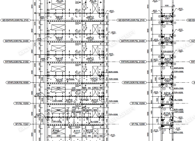
We provide GA Drawings and Marking Plans for:

Precast Beams

Wall Panels

Double Tee Slabs

Architectural Precast

Utility Precast

Precast Columns

Solid Precast Slabs

Hollow Core Slabs

Precast Double wall panels

Rebar Placing Drawings

Beam assembly drawing
Rebar Placing or Arrangement drawings are prepared to depict the quantities, bending shapes, dimensions, tying methods and placement of reinforced steel bars. We offer error free rebar GA drawings that enable the accurate fabrication and arrangement of the reinforcing bars. Bar bending schedules are also provided to the fixing and bending sequences. The rebar detailing team at Advenser has multi-country experience in developing the General Arrangement Drawings and Bar Bending Schedule from a wide range of residential, commercial and institution projects across North America to Australia. Our rebar detailers utilize a three tier quality assurance system to make sure to errors are left unspotted and strictly adhere to ACI, CRSI, RSIC and BS standards and specifications. Our international experience makes sure that the rebar drawings we produce, allow efficient perfect placement and consolidation of concrete between bars.

Check our samples.

Contact us Now.

Get a Quote