 BIM Services
 Architectural
 Structural
 MEP
MEP Facade
 Industrial
Piping and Instrumentation Diagrams (P&ID)
Advenser is an eminent service provider of piping and instrumentation diagram/drawing (P&ID) services embracing cutting-edge technology. Our team of efficient engineers has the relevant domain knowledge and assists clients in designing a manufacturing workflow for physical plants. Based on the schematized phases mapped out with our accurate P&ID, we facilitate our clientele with the construction of a plant design maintaining the essential safety standards. We also excel in creating highly precise P&IDs with the help of 3D laser-scanned data (point cloud data).
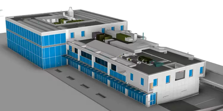
Piping and instrumentation diagrams (P&IDs) play a critical role for the process plants benefiting the stakeholders to get a detailed representation of the plant’s equipment. P&IDs are also vital for controlling plant processes as well as in the operation, maintenance, and system modification/updation of the processes.
Our detailed P&ID in the form of a graphical/schematic representation consists of the hardware and software i.e. comprehensive network of piping, instrumentation, system equipment, and specifications required to design, construct and operate the facility. These high-quality P&IDs enable the facility managers to have a correct perception of the relationship between the piping and instrumentation components at the plant and facilitate its effective functioning.
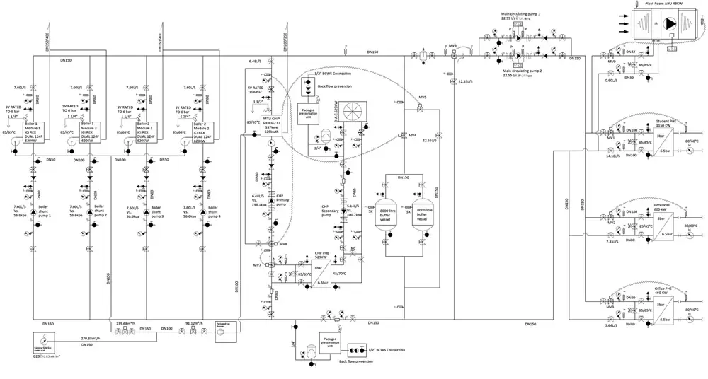

Our P&IDs Schematic Representation includes:
Mechanical equipment with names and numbering
Valves with their identities
Signals & Interconnections references
Quality level
Flow directions
Control inputs and outputs
Equipment assessments
Physical sequence of the equipment
Interfaces for class changes
Vents, drains, special fittings, sampling lines, reducers, increasers and sewage system
Our Piping and Instrumentation Diagrams (P&ID) projects include:
Oil and Gas Plant
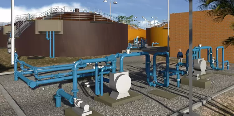
Water Treatment Plant
Water Purification Plant
Petrochemical Plant
Industrial
Healthcare
Our Piping and Instrumentation Diagrams (P&ID) deliverables comprise:
Development of Piping & Instrumentation Diagrams (P&IDs)
Point clouds to CAD conversion accurate P&ID creation
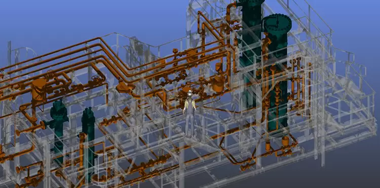
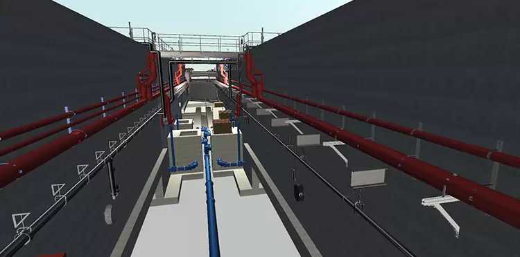
Detailed 3D modeling for piping arrangements
Construction documentation for piping systems
Pipe stress and flexibility analysis with Finite Element Analysis (FEA)
Frequently Asked Questions
How do P&ID engineering services support process design?
P&ID engineering services provide detailed diagrams that represent the relationship between piping, equipment, and instrumentation. These diagrams support process design by offering clear visuals for system layout, control sequences, and operational flow, ensuring efficient process control and safety compliance.
What is included in P&ID engineering services?
P&ID engineering services include the development of piping layouts, control valve placement, instrumentation details, equipment symbols, and process flow annotations. These drawings define the functional flow of the system, helping guide construction, installation, and maintenance.
When are P&ID diagrams required in the project lifecycle?
P&ID diagrams are required during the design phase for process systems, including piping, equipment, instrumentation, and control systems. They are critical for documentation, safety analysis, and troubleshooting throughout the project lifecycle.
How do P&ID diagrams support regulatory compliance?
P&ID diagrams support regulatory compliance by providing detailed representations of piping and instrumentation systems that meet safety, environmental, and operational standards. These diagrams are often required for approvals from regulatory bodies like OSHA, ASME, and local authorities.
Can P&ID diagrams be developed from 3D models?
Yes. P&ID diagrams can be developed from 3D models using data extracted from BIM or other engineering models. This integration ensures accuracy and consistency between design stages.
How accurate are P&ID diagrams?
P&ID diagrams are developed with precise symbol representation, dimensions, and process flow details to ensure operational accuracy. Quality control procedures ensure all data is consistent and reliable for use in construction, operation, and maintenance.
Which industries require P&ID engineering services?
P&ID engineering services are essential in industries like oil and gas, petrochemical, power generation, pharmaceuticals, and water treatment, where precise process control and safety are crucial.
How are P&ID diagrams used in maintenance and operations?
P&ID diagrams are used in maintenance and operations for system troubleshooting, equipment maintenance, and operational training. They provide a visual reference for system flow, control points, and critical equipment connections.
Can P&ID diagrams support system upgrades?
Yes. P&ID diagrams support system upgrades by providing an accurate representation of the existing system, making it easier to implement modifications, add new equipment, or change the flow of materials in compliance with updated designs.
How do P&ID engineering services reduce project risks?
P&ID engineering services reduce project risks by providing early identification of design conflicts, clear system layouts, and compliance with safety standards, ultimately minimizing costly delays and rework during construction and operation.
Check our work samples
Architectural, Structural, Mechanical, MEP/HVAC and Facade CAD and BIM samples
Contact us now
If you have any queries related to our services, feel free to contact us today itself.